Step 7.2: Leader End-Effector Sub-Assembly
warning
Prerequisites
Before starting the assembly, please configure motor IDs by following Step 1: Setup Motor ID.
- Attach
J8_AtoJ8_Busing 3M3x6bolts
- Insert two
M4x4 heat set insertsin theswivel_rotor_leaderusing a soldering iron.
- Insert one
M4x4 heat set insertin theright_pincerandleft_pincereach using a soldering iron.
- Insert 4
M3x6 heat set insertsin therail_connector_leaderusing a soldering iron.
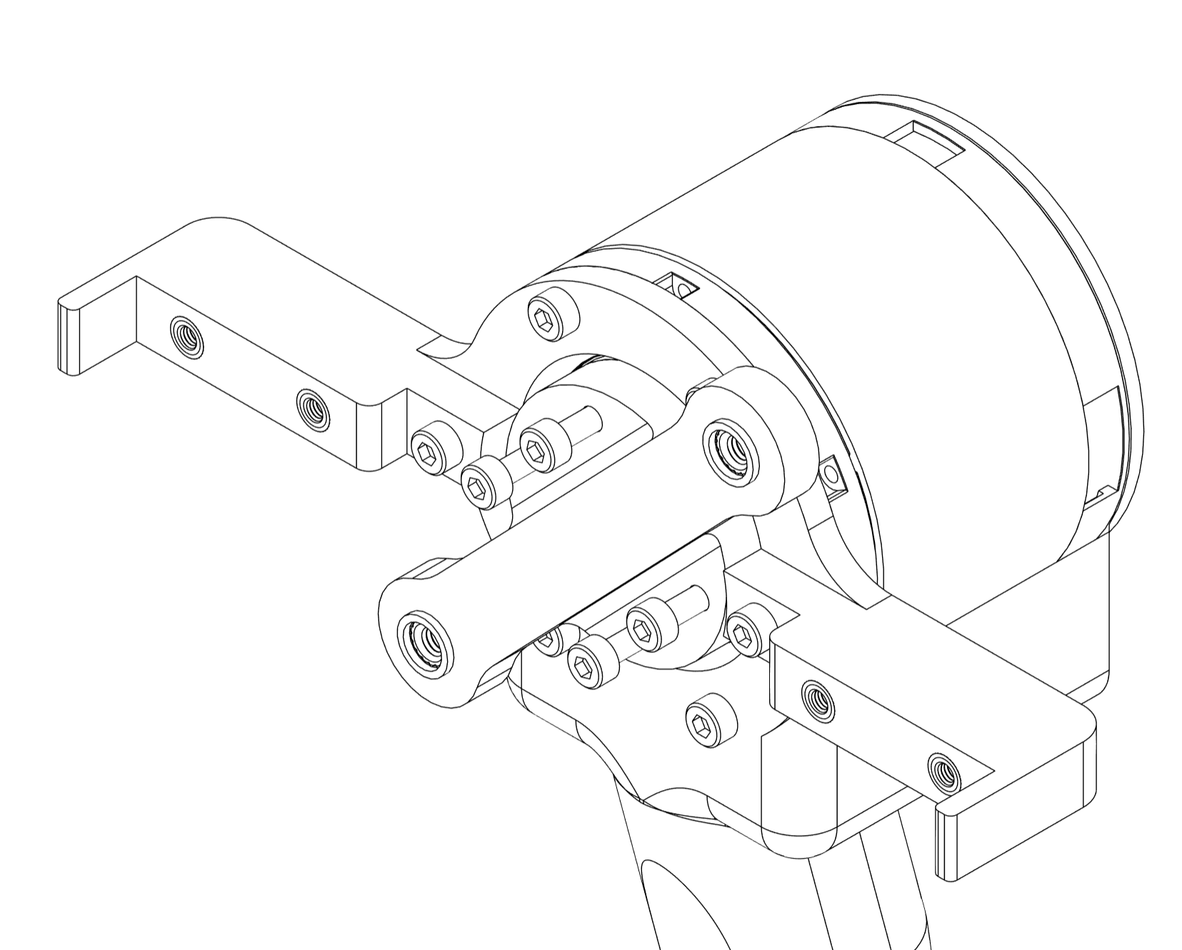
- Carefully insert bearings
MR126ZZintoswivel_link_leader. Note that two bearings need to be inserted from opposite directions.
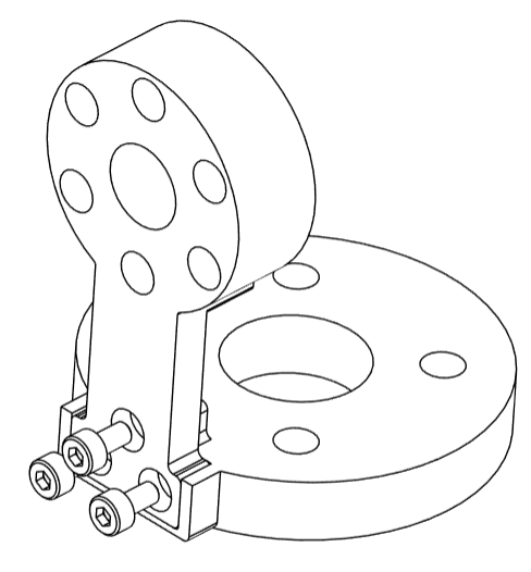
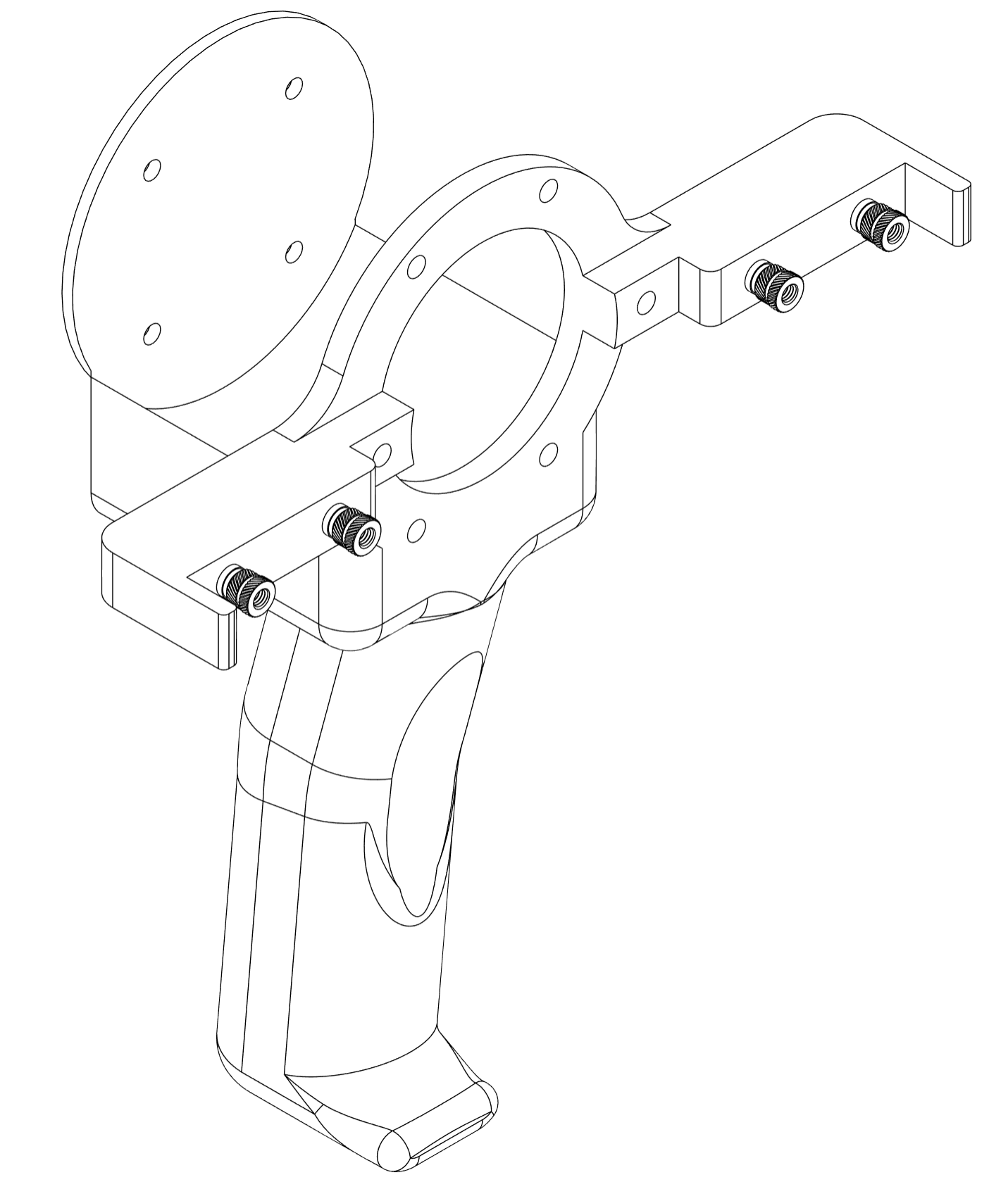
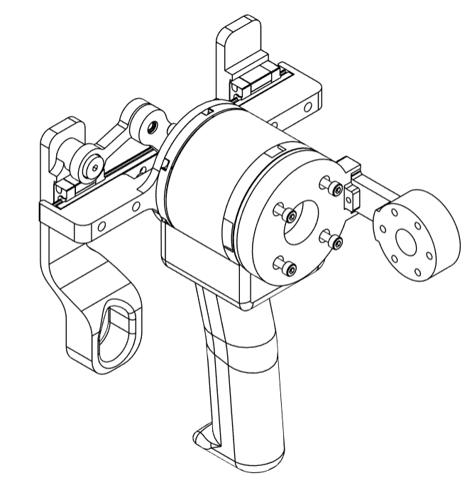
- Attach
rail_connector_leaderto theJ8motor using 4M3x8bolts as shown in the figure. Ensure that the flanges ofrail_connector_leaderare aligned to the two Power+CAN ports ofJ8
- Insert two
M3x15bolts along the flanges to fastenrail_connector_leadertoJ8motor.
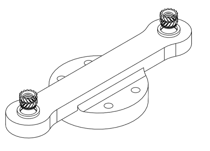
- Connect
swivel_rotor_leaderto the rotor ofJ8using 4M3x12bolts.
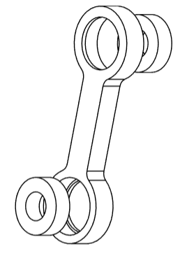
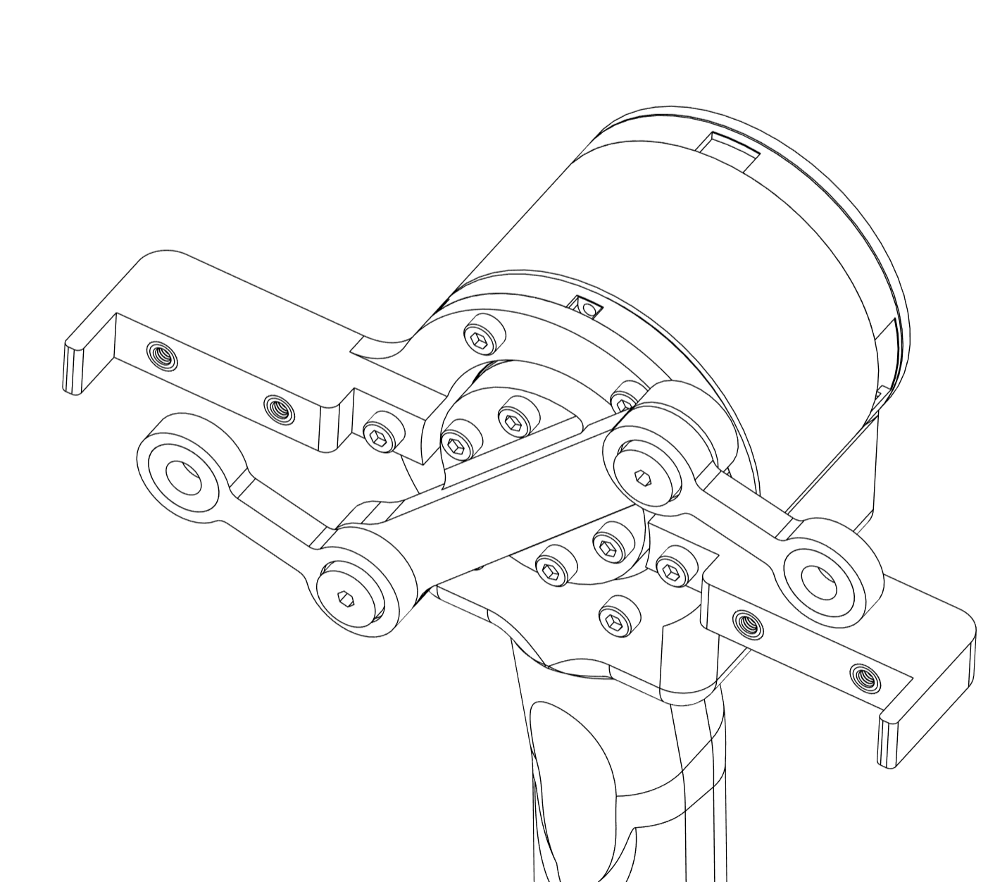
- Attach the two
swivel_link_leadercomponents to theswivel_rotor_leaderusing step boltsDBSY4-5-4. Make sure the bearings are oriented such that the fully exposed (open) side of each bearing faces toward theswivel_rotor_leader, as shown in the image. This orientation ensures proper alignment and freedom of movement for the linkages.
- Attach the linear guide to
rail_connector_leaderusing 4M3x6bolts.
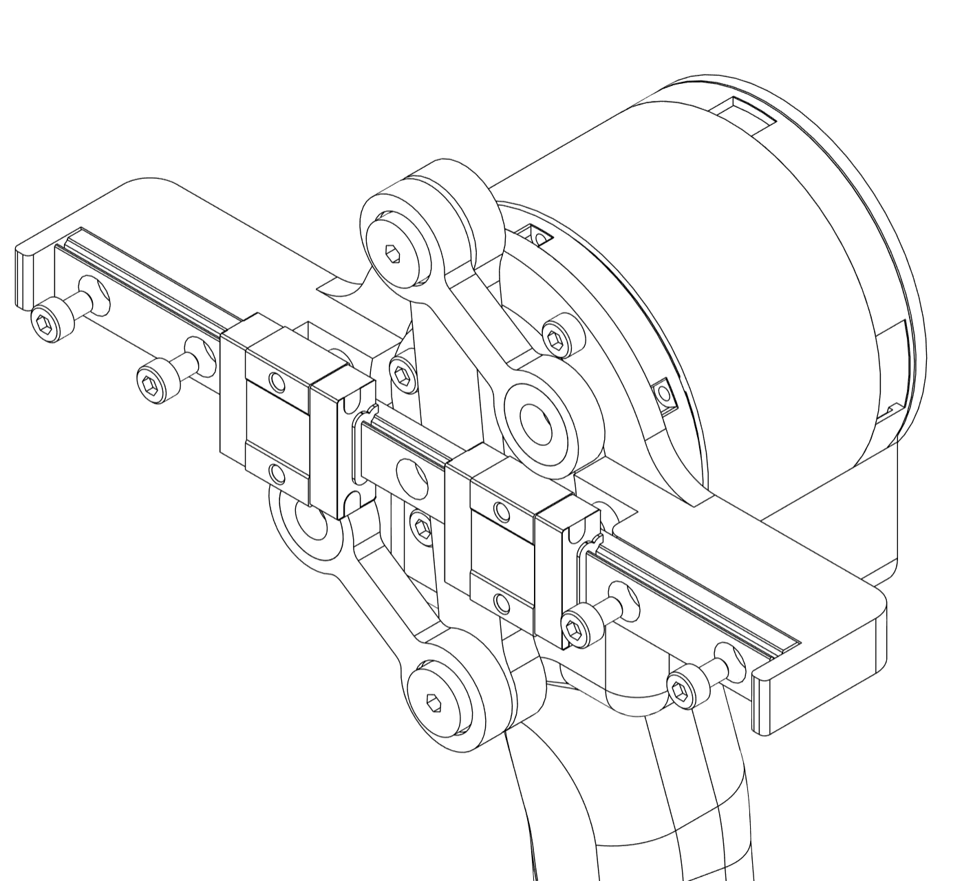
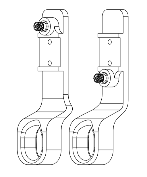
- Attach the
left_pincerandright_pinceron the slider blocks using 2M3x6bolts each. Ensure that the heat set insert is towards theswivel_link_leaderfor both the pincers.
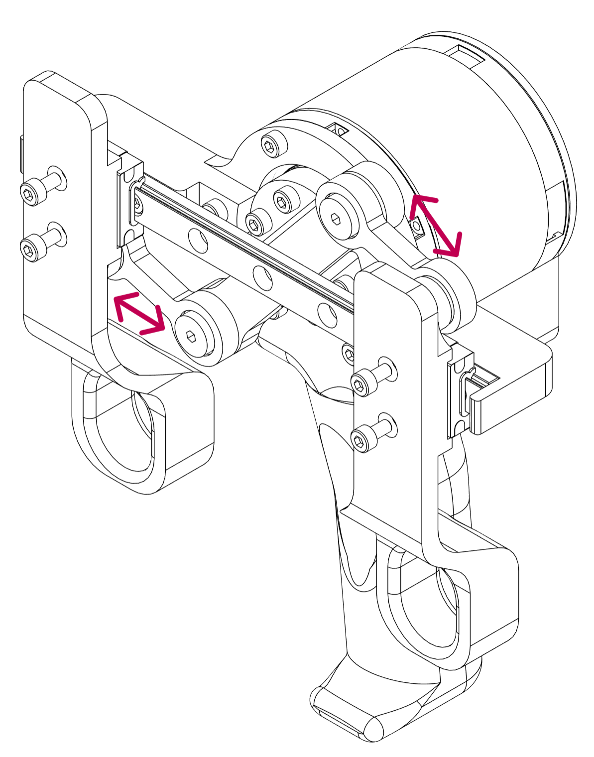
- Attach the
swivel_link_leadercomponents to theleft_pincerand theright_pincerusing step boltsDBSY4-5-4.
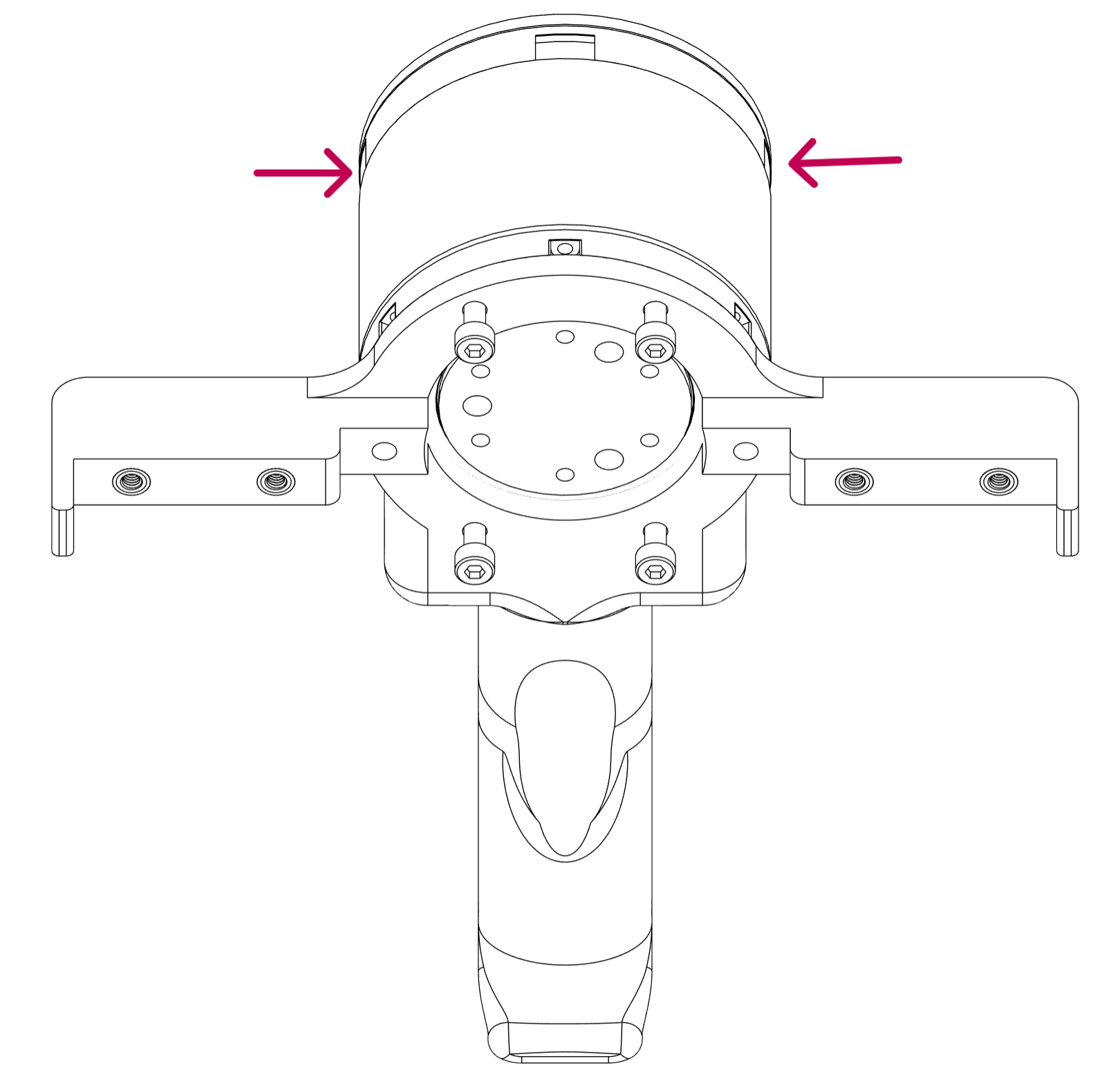
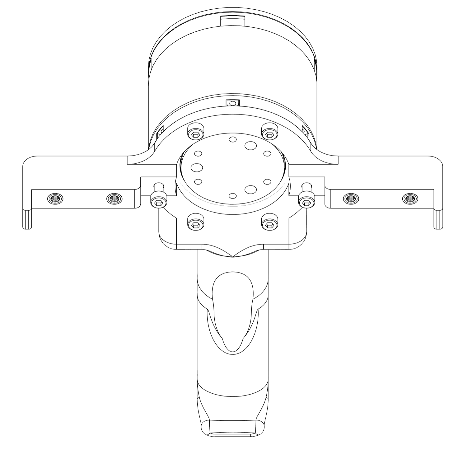
- Mount the subassembly created in Step 1 to the rear face of the
J8motor using fourM3×10bolts.
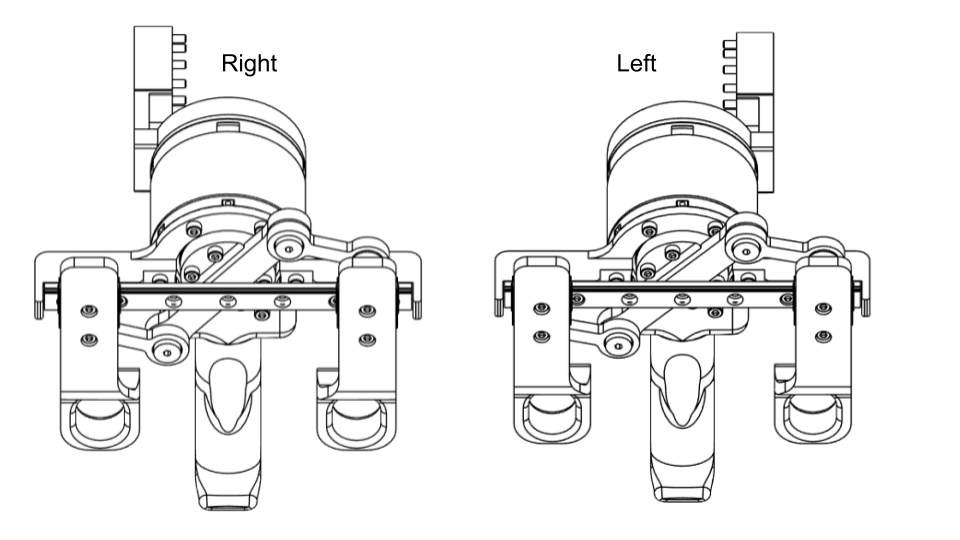
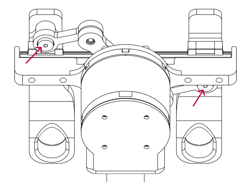
- When assembling the right arm, ensure the
J8_Apart is aligned with theright pincer. - When assembling the left arm, align
J8_Awith theleft pincer.
The alignment ensures proper mechanical coupling and correct orientation of the jaws during operation, as indicated by the arrows in the image.
info
That concludes the Gripper Sub-Assembly