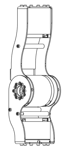
Step 5: J4-J5 Sub-Assembly
warning
Prerequisites
Before starting the assembly, please configure motor IDs by following Step 1: Setup Motor ID.
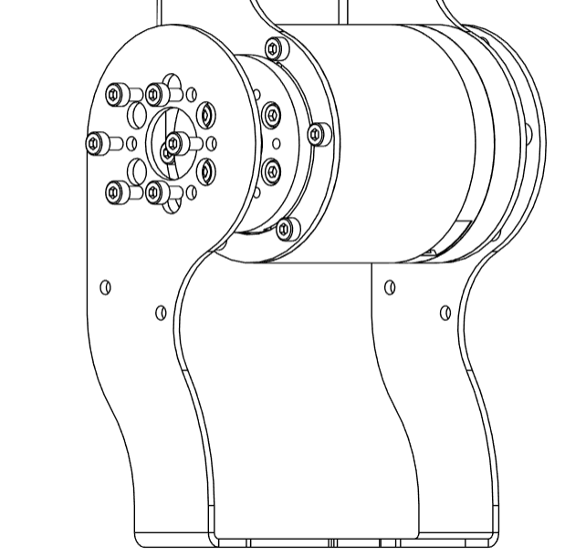
- Attach
J4_Cto the rotor ofJ4motor using 6M3x6bolts
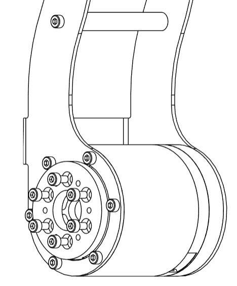
- Mount the component
J4_Donto theFL6803ZZ
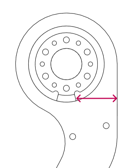
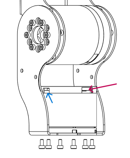
tip
Align the J4_E component vertically with the mechanical stop on J4_C, ensuring proper orientation before fastening.
- Attach the component
J4_EtoJ4_Cusing 6M3x6bolts.
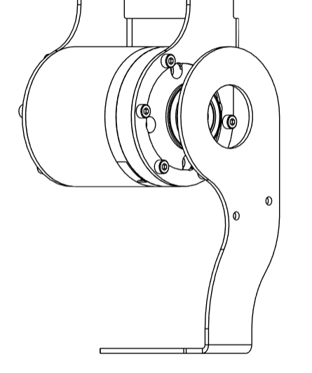
- Place the
J5motor between theJ4_DandJ4_Eand fasten them using 6M3x6bolts. Ensure that the Power+CAN ports are facing front and rear for effective wiring. Keep the communication port facing towards the partJ4_E.
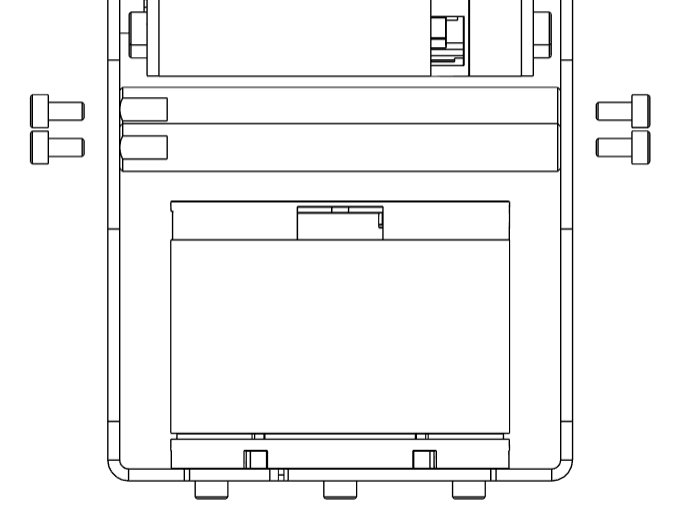
- Carefully place two posts
AETTS8-74.2-SC0-M3-N3between theJ4_DandJ4_Ecomponents, and fasten them usingM3x6bolts
info
That concludes the J4-J5 Sub-Assembly