Step 6: J5-J6-J7 Sub-Assembly
warning
Prerequisites
Before starting the assembly, please configure motor IDs by following Step 1: Setup Motor ID.
- Install the
FL6700ZZbearing into the sheet metal componentJ6_A, and gently insertJ7_Binto the bearing, aligning it as shown in the figure.
- Repeat the procedure with
J6_B
- Attach
J5_Ato the rotor ofJ5motor using 6M3x18bolts
- Attach the
J6_Bcomponent toJ5_Ausing 3M3x8bolts. Ensure thatJ6_Bis aligned towards the mechanical stop ofJ5_A
- Attach the component
J6_AtoJ5_Ausing 3M3x8bolts.
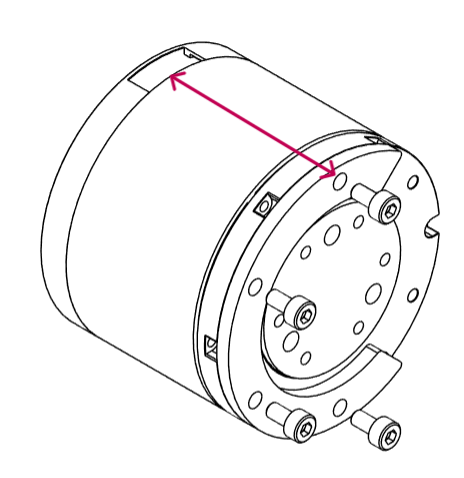
- Attach component
J6_Dto motorJ6using fourM3x6bolts. Ensure thatJ6_Dis aligned so its top and bottom line up with the two Power+CAN ports.
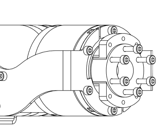
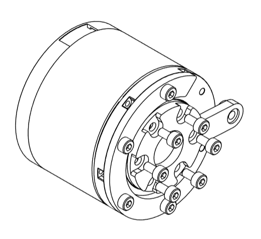
- Attach
J7_Eto the rotor ofJ6using 6M3x6bolts
- Carefully place the motor
J6betweenJ6_AandJ6_B, and securely fasten it toJ6_Ausing 4M3x6bolts. As a check, the communication port should be in line withJ7_E
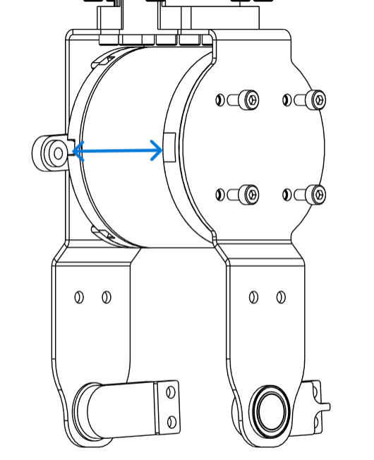
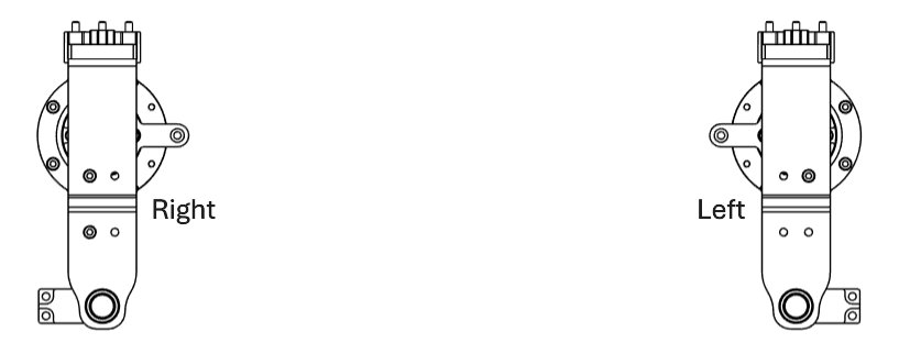
tip
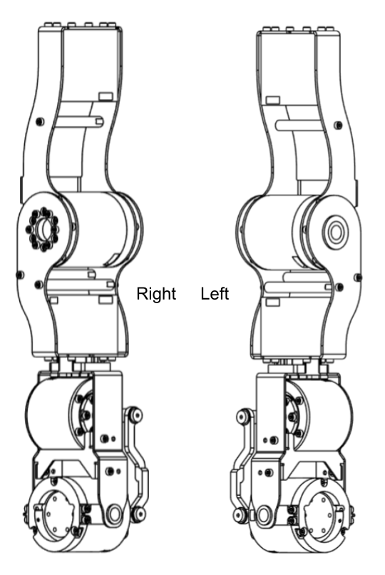
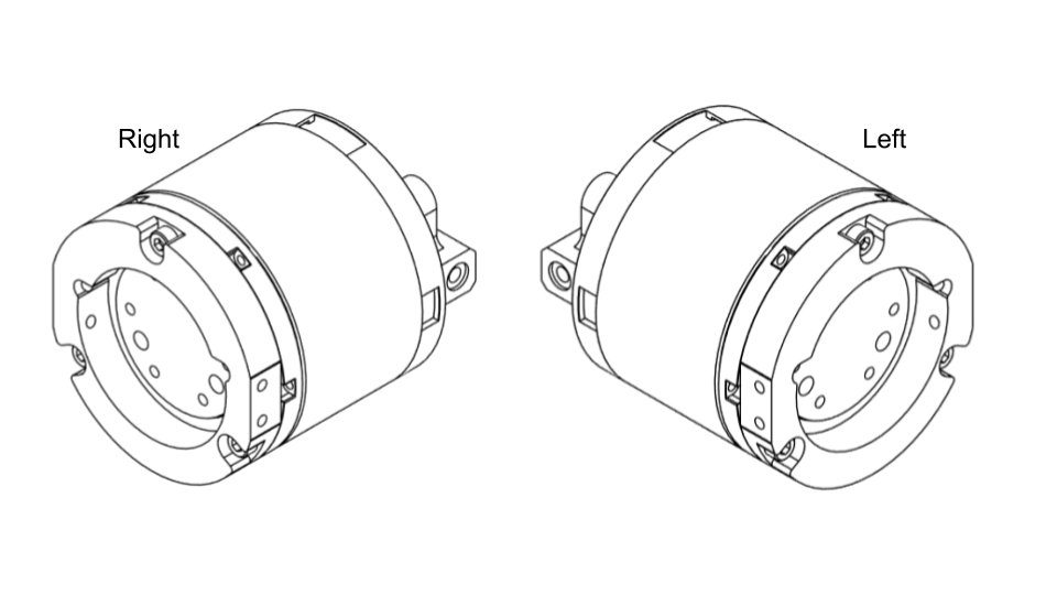
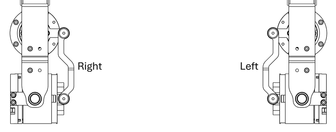
When looking straight at J6_B, J7_E should be protruding to the right for the right arm, and to the left for the left arm.
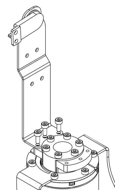
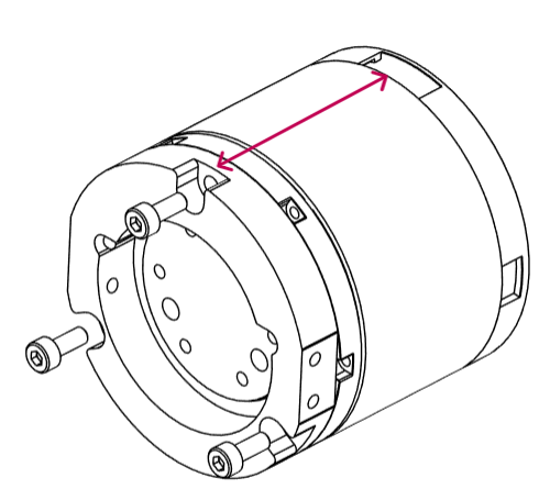
- Attach part
J7_Ato theJ7motor using threeM3x8bolts. Make sure the orientation matches the image, with the top bolt aligned with the Power+CAN port.
- Using two
M3x8bolts, mount partJ7_Cto the back of motorJ7as shown. Check that it’s aligned correctly and runs parallel to the line between the two Power+CAN ports.
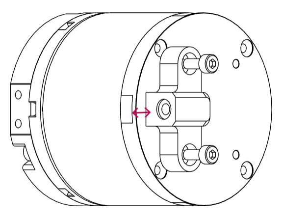
tip
While assembling the left arm, mount the part J7_C on the opposite side.
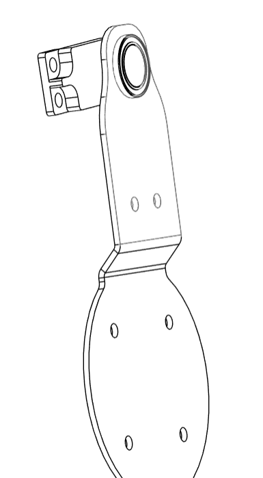
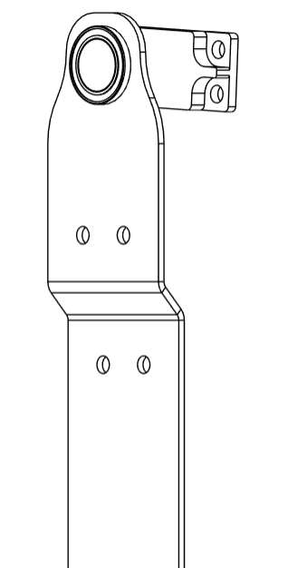
- Insert bearings
MR106ZZ1into the two holes of partJ7_D_right.
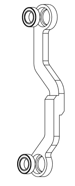
tip
For assembling the left arm, use the part J7_D_left.
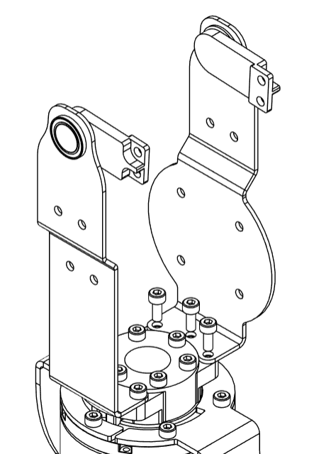
- Carefully place the motor
J7between theJ6_AandJ6_Bsheet metal pieces, and attach the twoJ7_Bpieces toJ7_Ausing 2M3x8bolts on each side.
tip
J7_C and J7_E should face the same direction once this step is completed
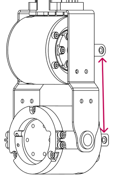
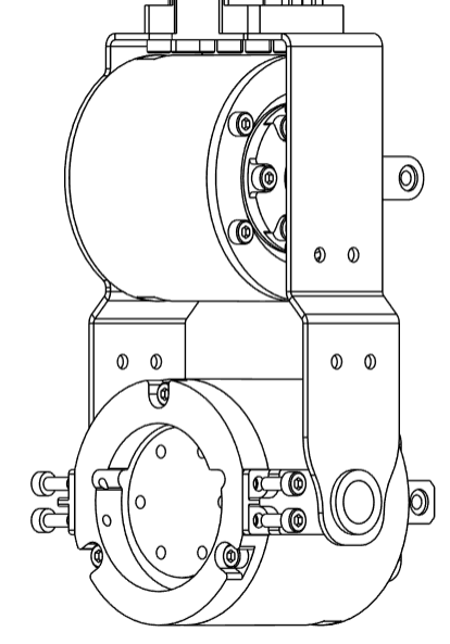
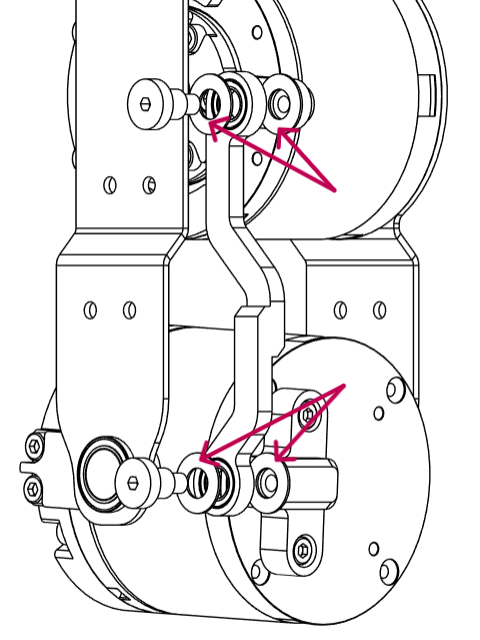
- Attach the component
J7_D_rightto bothJ7_CandJ7_Eusing the step boltDBSY4-6-5with 4 washersSWSPS12-6-0.5between the step bolt andJ7_Das well asJ7_DandJ7_C/J7_E.
tip
While assembling the left arm, use the part J7_D_left.
- Carefully insert
J6_C_rightpart betweenJ6_AandJ6_Band secure them using 3M3x6bolts
tip
When assembling the left arm, use component J6_C_left.
info
That concludes the J5-J6-J7 Sub-Assembly