Step 1: Setup Motor ID
Before running any further steps, we need to first ensure that the motor sender id (CAN ID) and receiver id (MASTER ID) are configured as the table below.
| Joint | Sender CAN ID | Receiver (Master) ID |
|---|---|---|
| J1 | 0x01 | 0x11 |
| J2 | 0x02 | 0x12 |
| J3 | 0x03 | 0x13 |
| J4 | 0x04 | 0x14 |
| J5 | 0x05 | 0x15 |
| J6 | 0x06 | 0x16 |
| J7 | 0x07 | 0x17 |
| J8 (Gripper) | 0x08 | 0x18 |
This guide explains how to configure (otherwise known as flashing) Damiao motors for use in OpenArm. It walks through installing the debugging tool, assigning motor IDs, and connecting power and CAN wiring. Excerpted from: https://wiki.seeedstudio.com/damiao_series/
Motor ID configuration can also be accomplished via direct CAN frame transmission if you know the existing ID (usually 0x01), however this approach is not included in this tutorial.
Install Damiao Debugging Tools
In Windows: Download the Damiao Debugging Tools

If Windows Defender blocks it:
- Open Windows Security
- Head to Virus & Threat Protection
- Click Protection History
- Locate the blocked file entry (should mention the Damiao Debugging Tools)
- Click Actions → Allow
- Rerun the installation
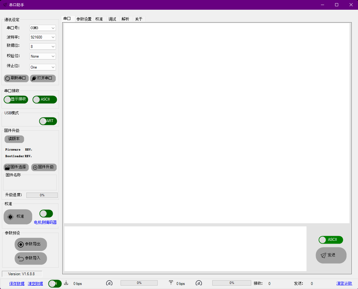
Running it should open a window like so: (Toggle English with the green/red toggle button at the bottom left.)
Using the Software
The tool is used for:
- Configuring IDs
- Quick calibrate to test if the motor runs
- Firmware version and control mode check before sending commands
:::tip Hardware Setup You might want to connect all the hardware components first using the reference below: Hardware Setup → :::
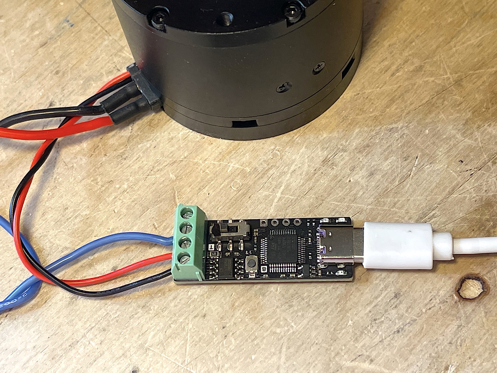
Open the Port
- The Damiao Debugging Tool communicates via serial (UART), not CAN.
- The serial connection runs at 921600 bps.
If it does not detect the correct serial port, it's usually the last one in the drop-down list.

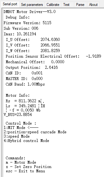
You can see the motor info on initial boot:
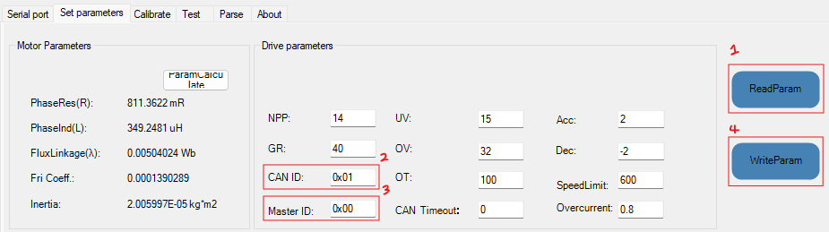
Configure Motor IDs
- Click ReadParam to pull parameters from the motor.
- In the ID table above, choose the correct Sender and Master ID.
- Input those values into the fields.
- Click WriteParam to save the settings to the motor.
Configure Damiao motor IDs before running any code on the arm.
Testing
Simple Calibration
Hit calibrate, and the motor should start moving. You don't have to save the results, but the identified parameters can be informative.

Advanced Testing
In the Test tab:
- Under CAN ID, set CAN IDs by clicking Read with the motor connected. If you have multiple motors daisy chained together, you can control all of them by setting the CAN ID to the last motor in the chain.
- Under Control Commands, click Enter to start the motor. (Redo every time the motor reboots, the LED above the GH1.25 3-pin port should glow green)
- Under Control Parameter, set your values. A simple test is to set the Tor (torque) to a value like 1. For other controls, refer to the official motor documentation
- Under CAN Data, click Update to pull the values from Control Parameter. (Redo whenever you input new values)
- Under CAN Data, click Send to send the values to the motors and have them start spinning.
- To stop, set the values under Control Parameter to 0 and Update. Simply clicking Stop will hard stop the motors, only do in case of emergency.
Trouble Shooting
- If the motor starts but fails to rotate: Check the current provided and compare if you're supplying enough with this table below
- For CANable devices, check whether the 120Ω termination is enabled.
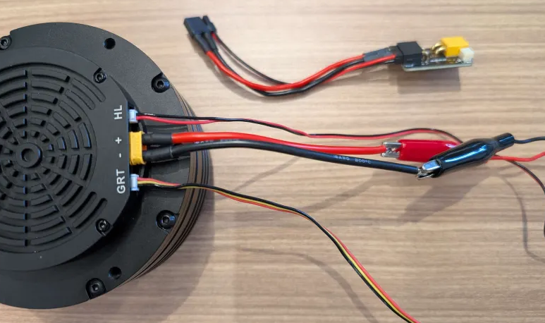
Hardware Setup
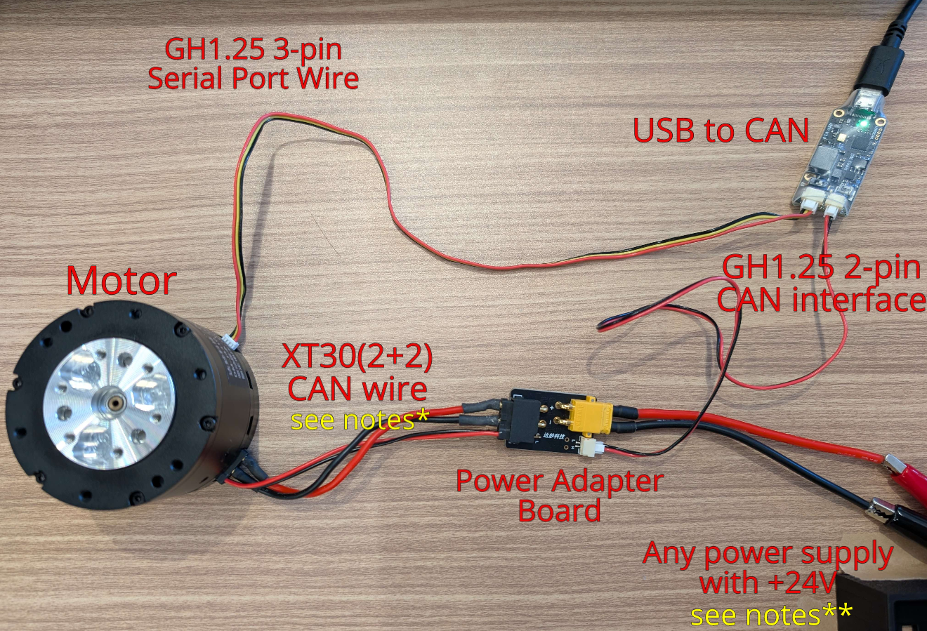
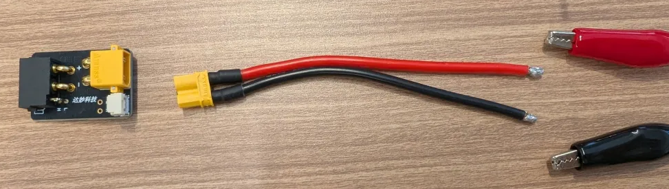
You might need to solder another male connector if you are using the cables in the motor package.
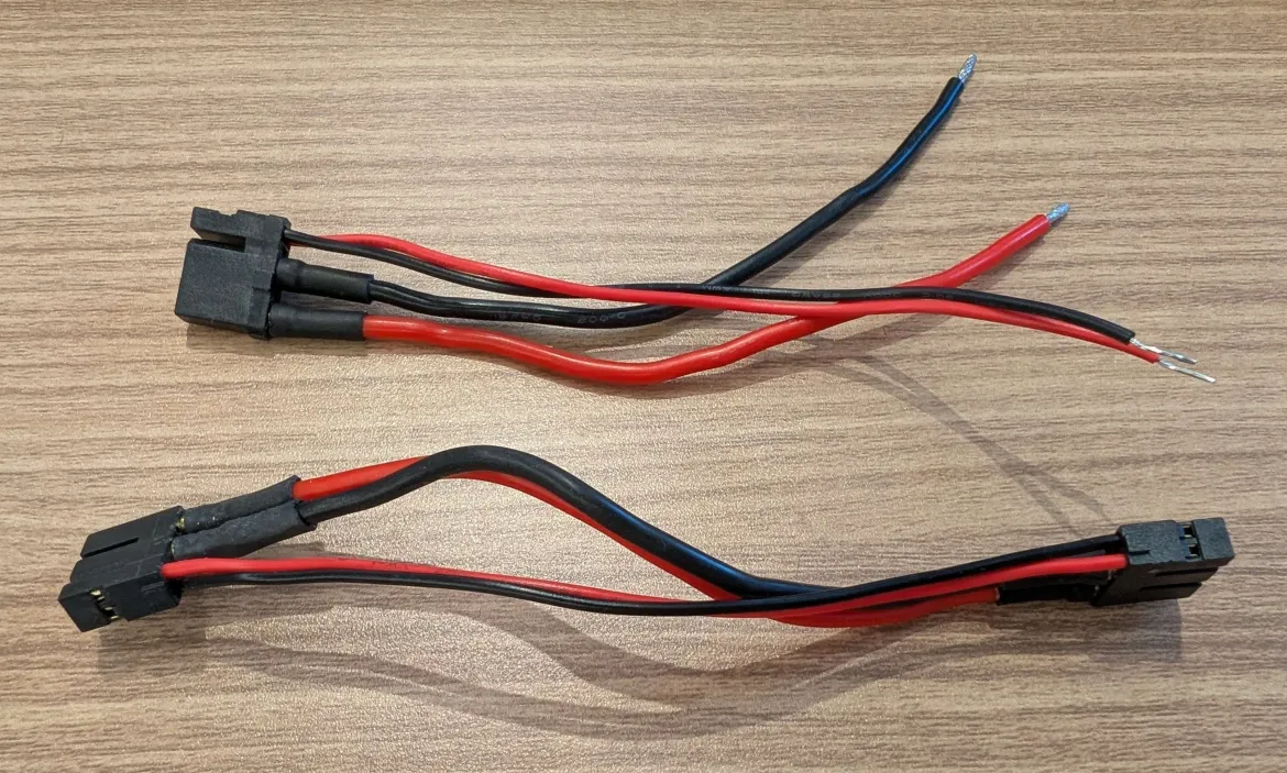
One option is to use an XT30U-M or split a M/F cable and solder the ends to connect with a 24V PSU.
For the J8009P motors, you can plug the wires directly in without the power adapter board.
For CANable devices, enable the 120R termination.
Reccomended Currents:
Current Table For Calibrating and Testing @ 24V:
| Motor | Minimum Current | Reccomended Current |
|---|---|---|
| DM-J4310 | ~0.25 A | ~0.3 A |
| DM-J4340 | ~0.25 A | ~0.3 A |
| DM-J8009P | ~0.7 A | ~0.75 A |
Current is additive so if you daisy chain motors together, you would need to provide the sum of the currents needed.