Step 8: Final assembly
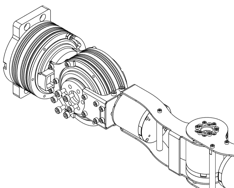
- Attach
J2-J3 Sub-Assemblyto the rotor ofJ3motor using 6M3x15bolts
- Attach
J2_Ato the rotor ofJ2motor using 6M5x10bolts.
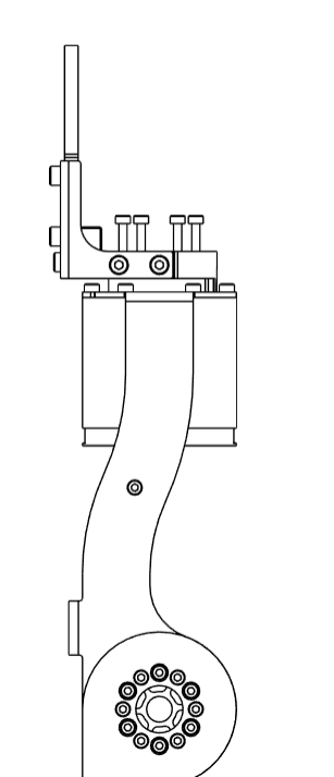
- Connect the
J8_Acomponent from theGripper Sub-Assemblyto the rotor ofJ7motor using 6M3x15bolts.
tip
When assembling the leader arms, attach the J8_A component from the Leader End-Effector Sub-Assembly.
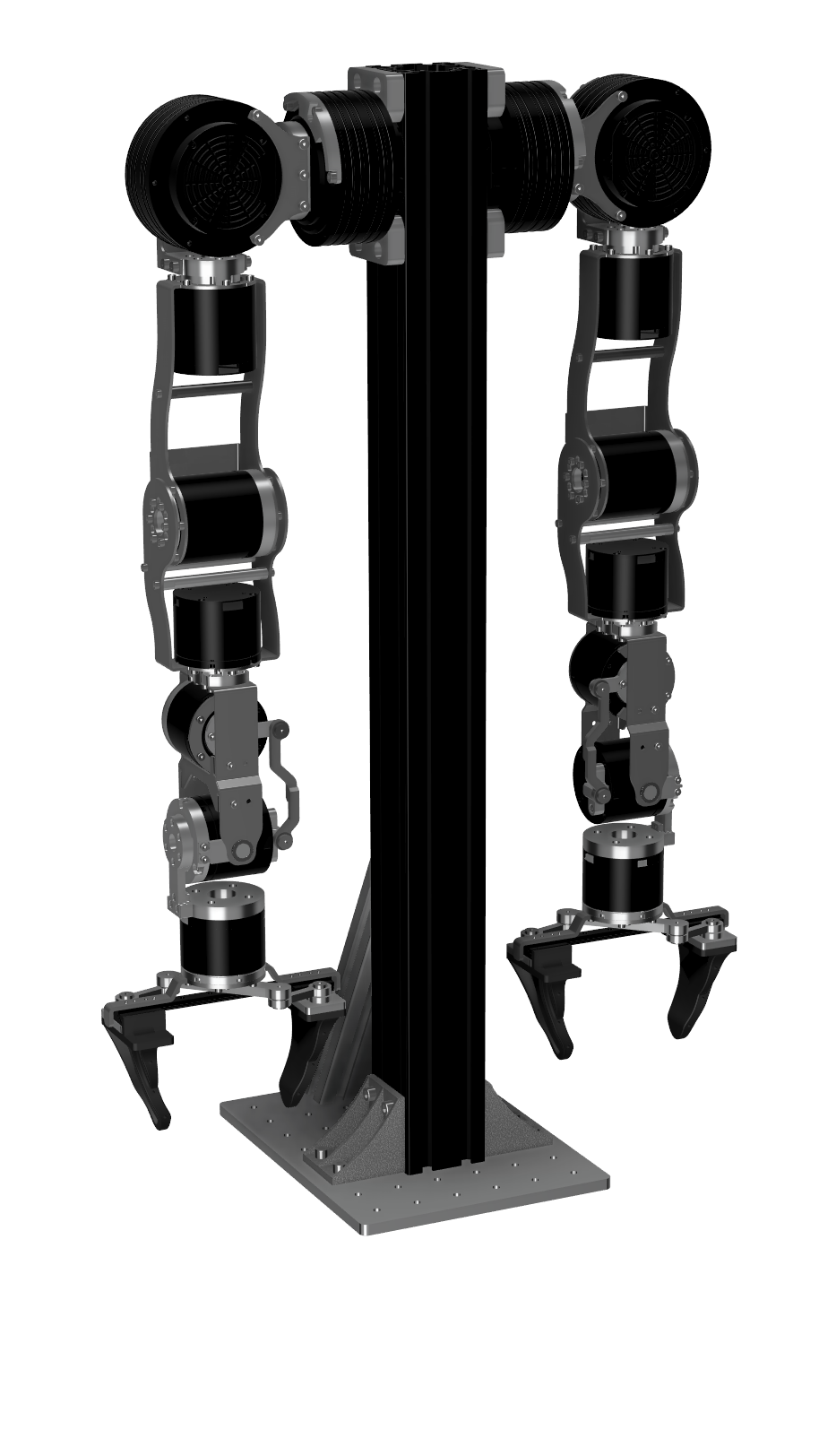
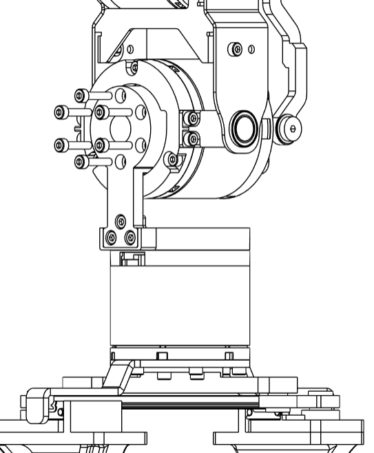
- Finally, mount the arms on the pedestal using 4
M6x12bolts inJ1_A. Make sure you have already inserted T-slot nuts inside the aluminium extrusion. Align the top ofJ1_Ato the top of the aluminium extrusion.
tip
The Power+CAN ports of the J1 motor of both the arms face the front. The reinforcement in the pedestal is towards the back.
info