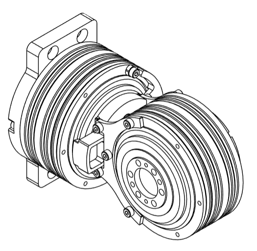
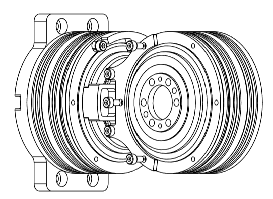
Step 2: J1-J2 Sub-Assembly
warning
Prerequisites
Before starting the assembly, please configure motor IDs by following Step 1: Setup Motor ID.
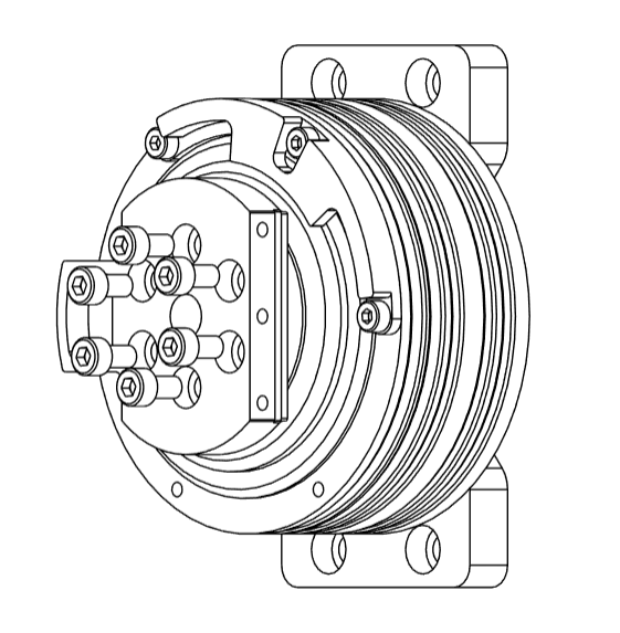
- Attach the rear of the
J1motor toJ1_Awith 5M4x10bolts. Ensure the power and communication ports remain accessible. Ensure that this motor has been configured to haveID:0x01andMaster ID:0x11
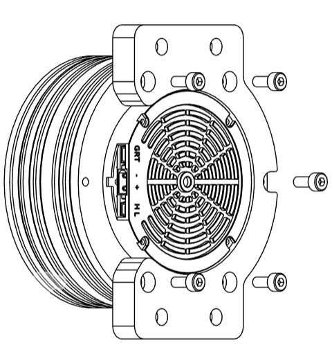
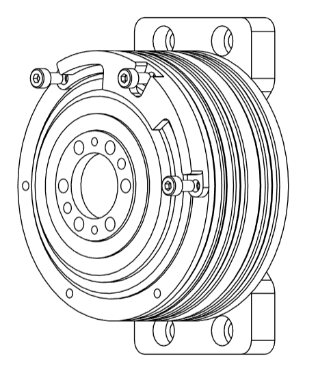
- Attach
J1_Bto the motor using 3M4x8bolts. The mechanical stop should face the motor’s power port and be on the top side. Refer to the image for clarity.
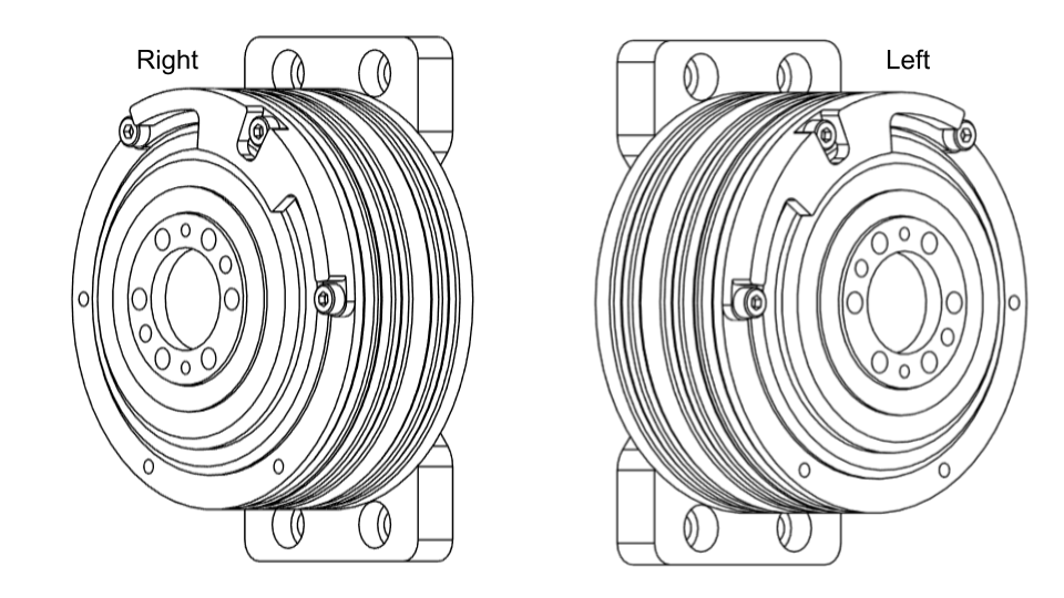
tip
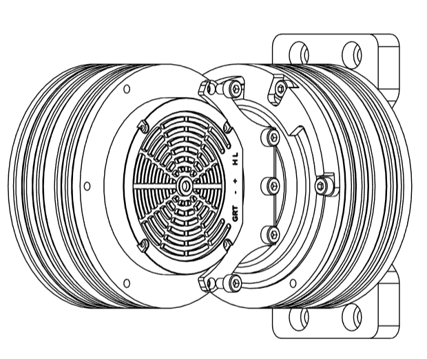
For the left arm assembly, part J1_B must be oriented slightly differently. Please refer to the image for the correct orientation. All other steps remain unchanged. Ensure that the Power+CAN ports on the J1 motor face forward, with the mechanical stop positioned toward the ports and at the top.
- Attach the
J1_Cpart to the rotor ofJ1using 6M5x10bolts
- Attach
J1_DtoJ1_Cusing 2M4x10bolts
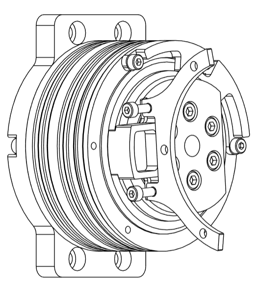
- Attach
J1_EtoJ1_Cusing 3M4x10bolts
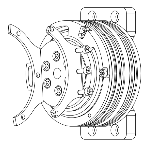
- Carefully insert the DM8009 motor
J2betweenJ1_DandJ1_E, with the ports facing directly towardJ1. The rear ofJ2should faceJ1_E. JoinJ1_EtoJ2motor using 2M4x8bolts
- Attach
J1_DtoJ2using 3M4x8bolts
info
That concludes the J1-J2 Sub-Assembly