Step 4: J3-J4 Sub-Assembly
warning
Prerequisites
Before starting the assembly, please configure motor IDs by following Step 1: Setup Motor ID.
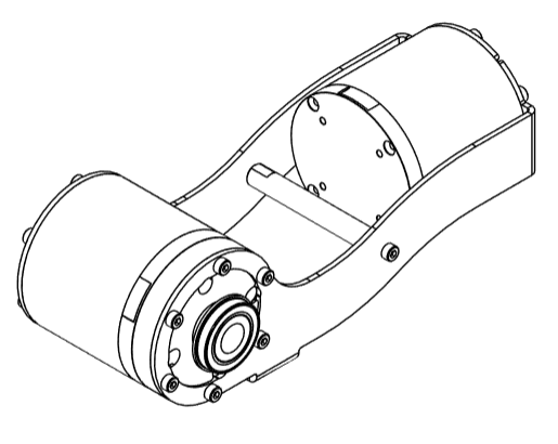
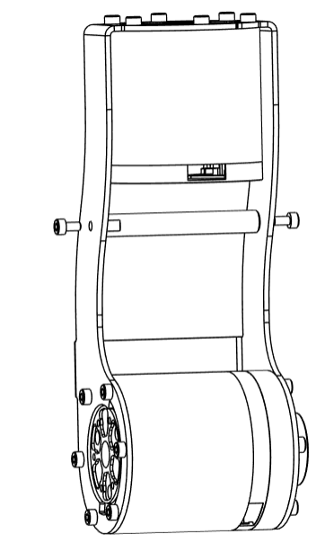
- Attach
J4_Ato theJ3motor using 6M3x6bolts. Make sure the two Power+CAN ports face the front and rear for easy wiring.
tip
Keep the communication port of the J3 motor to the right side
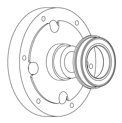
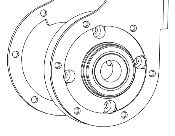
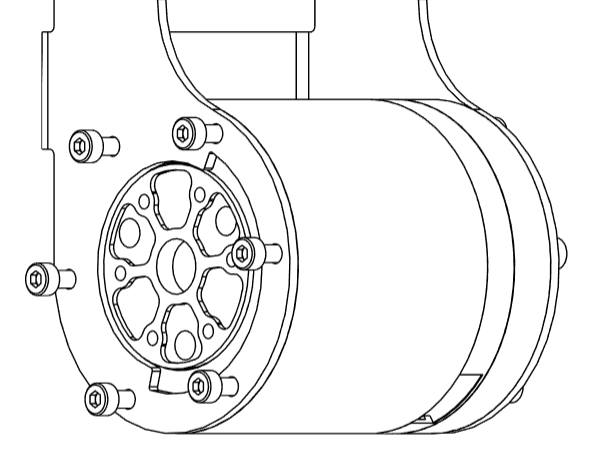
- Mount the bearing
FL6803ZZontoJ4_B
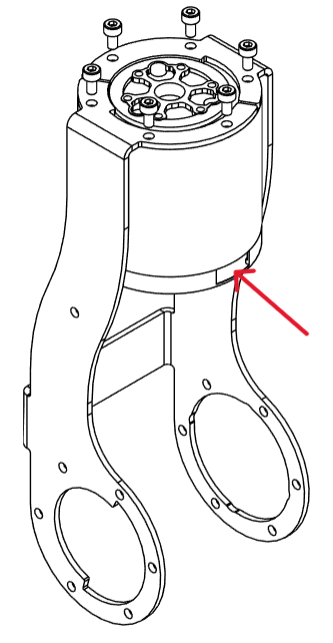
- Place the
J4_Bon the interior side ofJ4_A,aligning the holes. Do not fasten them yet.
- Carefully slide the
J4motor betweenJ4_AandJ4_B. Align it with the holes onJ4_B. Refer to the photo for correct positioning of the Power+CAN port. Fasten the motorJ4with partJ4_Busing 4M3x6bolts.
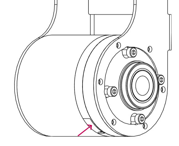
tip
Keep the communication port of the J4 motor to the position as shown in the figure.
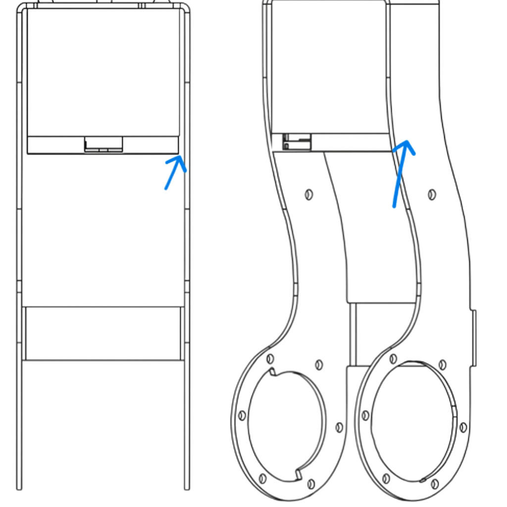
- Fasten
J4_AintoJ4_Busing 6M3x6bolts
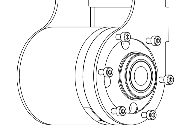
- Finally, fasten
J4_Ato the motorJ4using 6M3x6bolts.
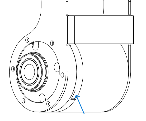
- Carefully insert the post
AETTS8-61-SC0-M3-N3between the flanges ofJ4_Aand fasten them with 2M3x6bolts
info
That concludes the J3-J4 Sub-Assembly