3. Chest Wiring & Casing
This section covers installing the hub boards, connecting all cables, and closing the chest cover.
For a list of components with photos, see section 0. Components.
Steps
1. Hub Board Installation
- Insert the HNTP6-6 T-slot nuts into the slots at the back of each shoulder.
- Attach the hub board back cover and hub board PCB using cap screws. Position the CAN connectors facing inward (toward the center of the body).
- Tighten all cap screws securely.
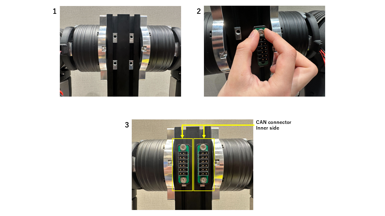
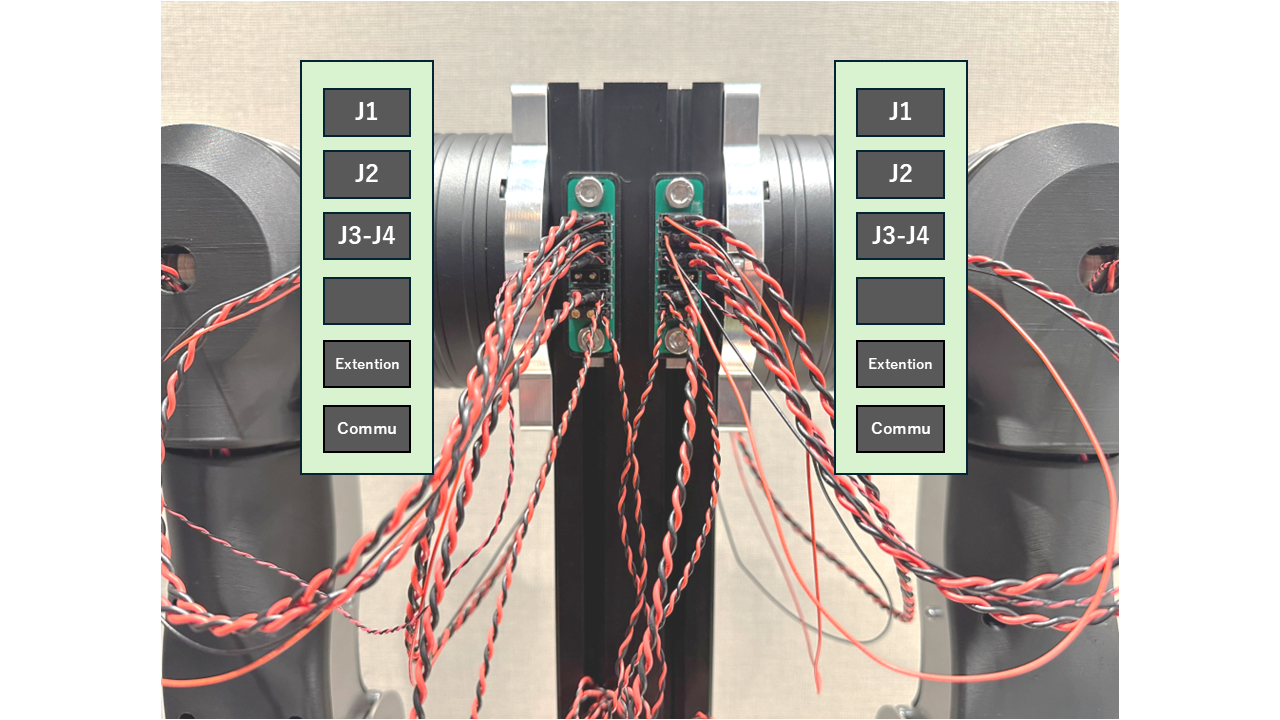
The left and right arms are separate systems. Each hub board operates independently.
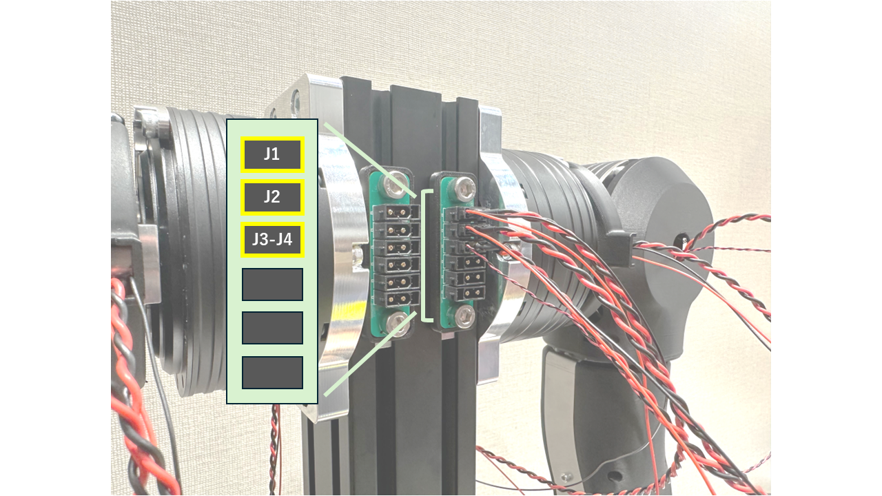
2. Hub Board Connection
Connect the J1, J2, and J3-J4 motor cables to the hub board as shown.
Connect the communication cables to the hub board as shown.
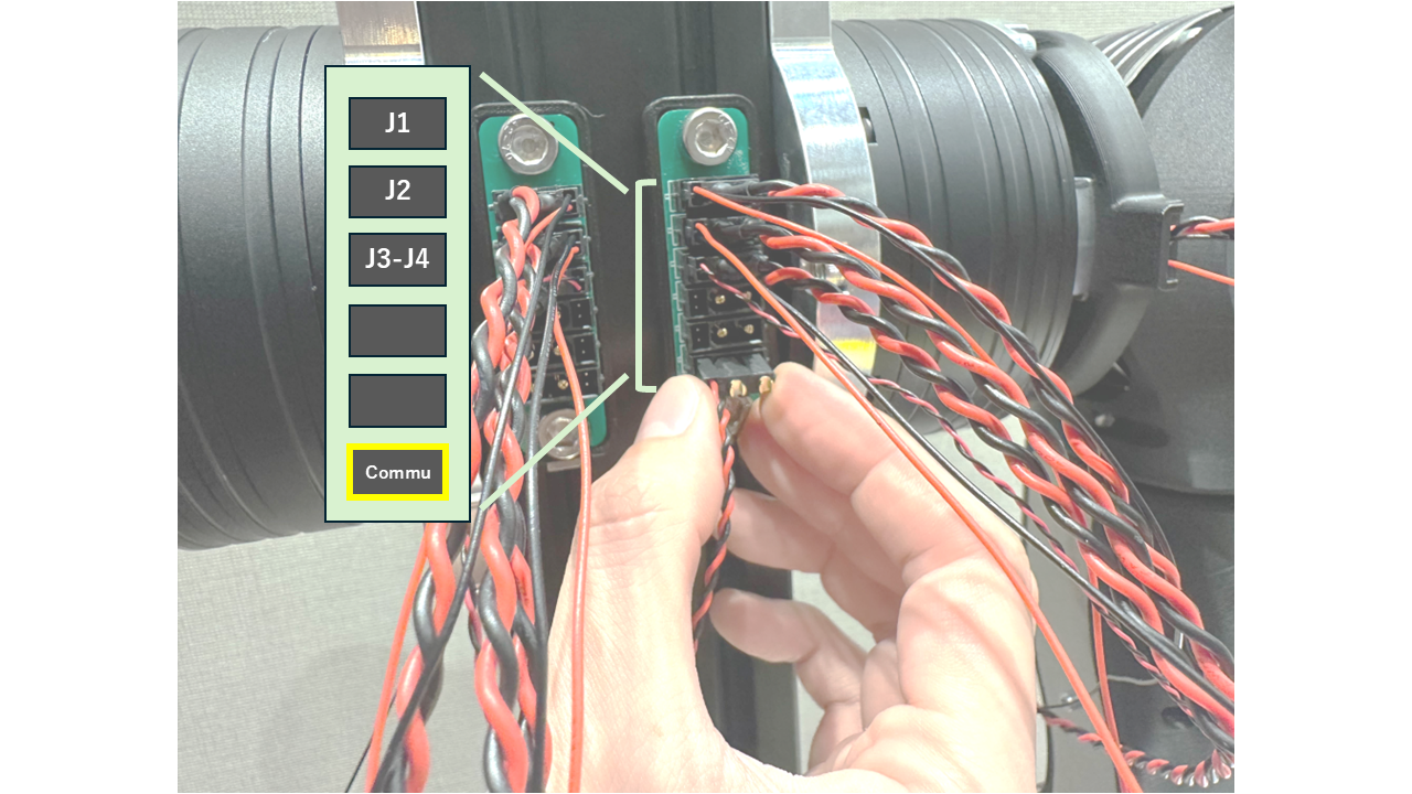
Connect the extension cables to the hub board as shown.
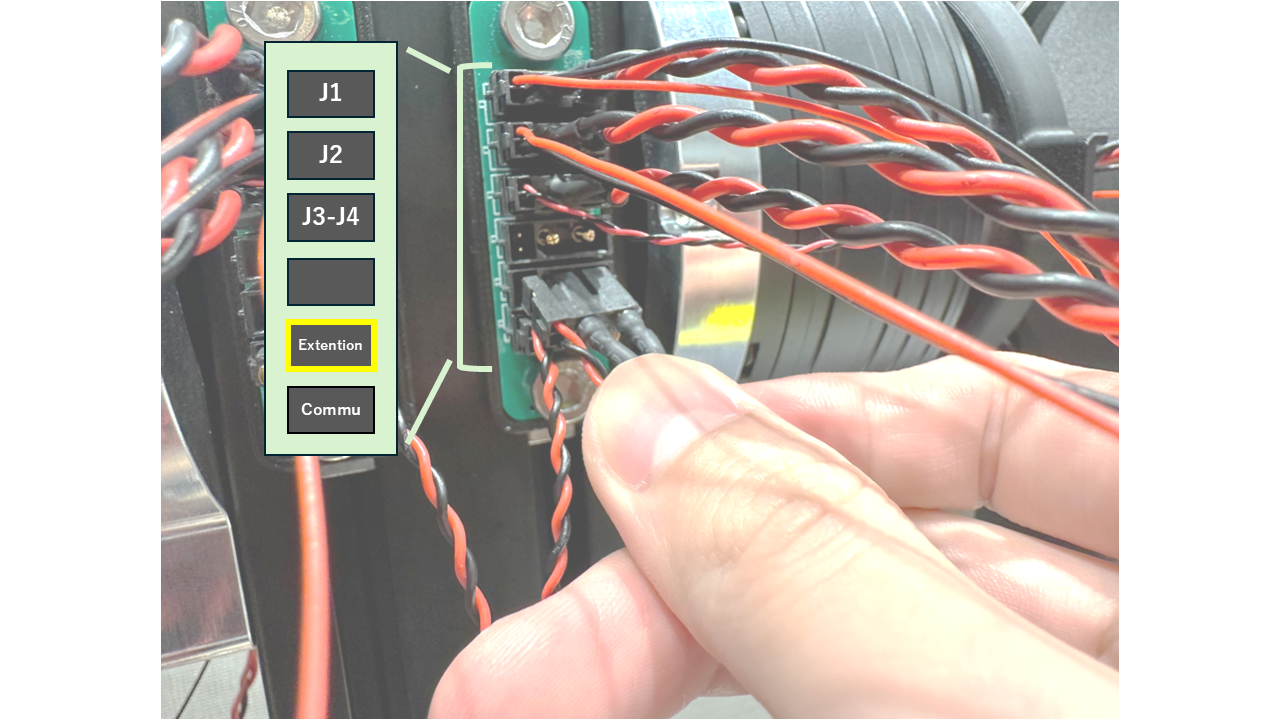
Verify that your wiring matches this reference image. Once all connections are confirmed, organize the cables neatly before closing the chest cover.
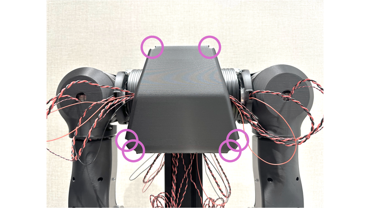
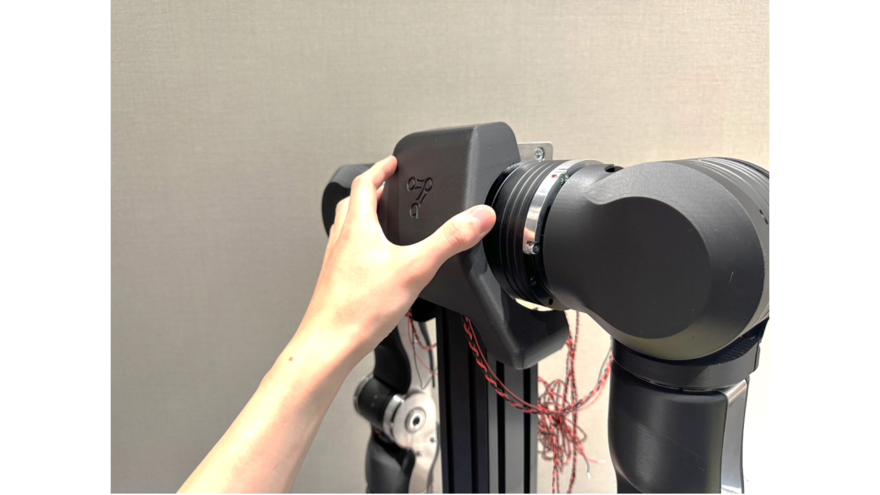
3. Chest Cover Installation
Attach Chest-cover_A from the front of the body.
Attach Chest-cover_B from the back. Route the J2 and J3-J4 cables through the U-shaped slots in Chest-cover_B.
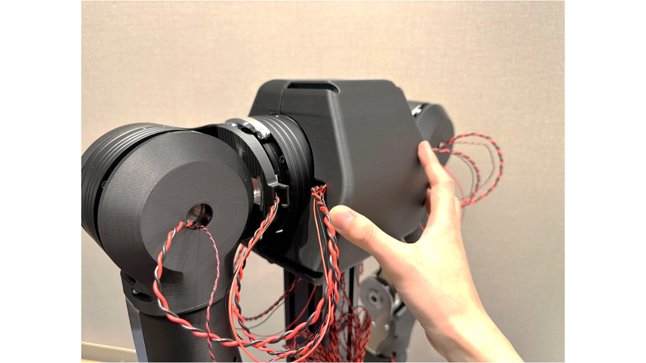
Be careful not to pinch any communication or extension cables between the body and the chest cover.
Use six screws to secure the chest cover.