1. Arm Wiring
Wiring Steps
The connectors are delicate, and applying excessive force when inserting or removing the cable may cause damage. Always hold the connector itself when plugging in or unplugging the cable, and avoid pulling on the wires.
Before you start
The J3–J4 and J4–J7 wirings can be a bit tricky. Please refer to the wiring topology shown below. Before starting, make sure to verify the pin assignments of all connectors.
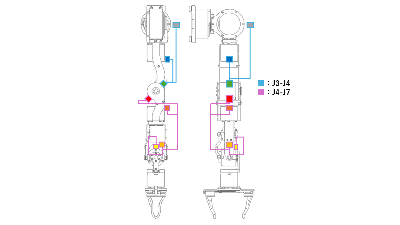
| J3-J4 Cable | J4-J7 Cable |
|---|---|
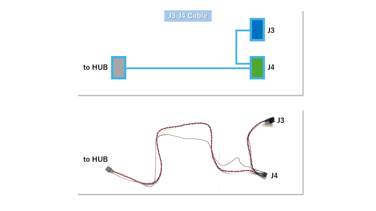 | 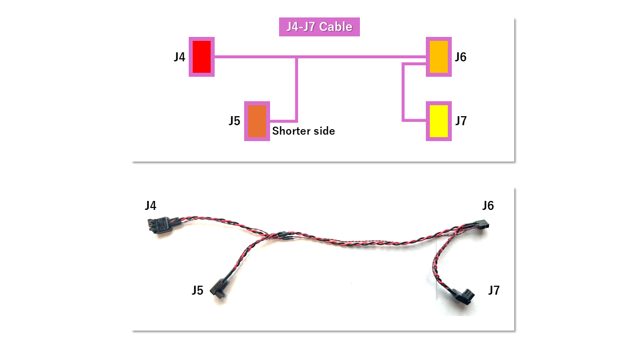 |
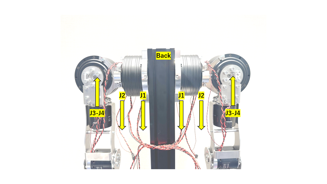
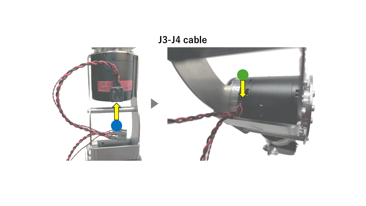
1. J3-J4 Wiring
Connect the J3 connector to the J3 motor (upper arm) and the J4 connector to the J4 motor (elbow). Route all cables along the back side of the upper arm. Since the J4 connector is located close to the sheet metal, be careful not to damage the cable.
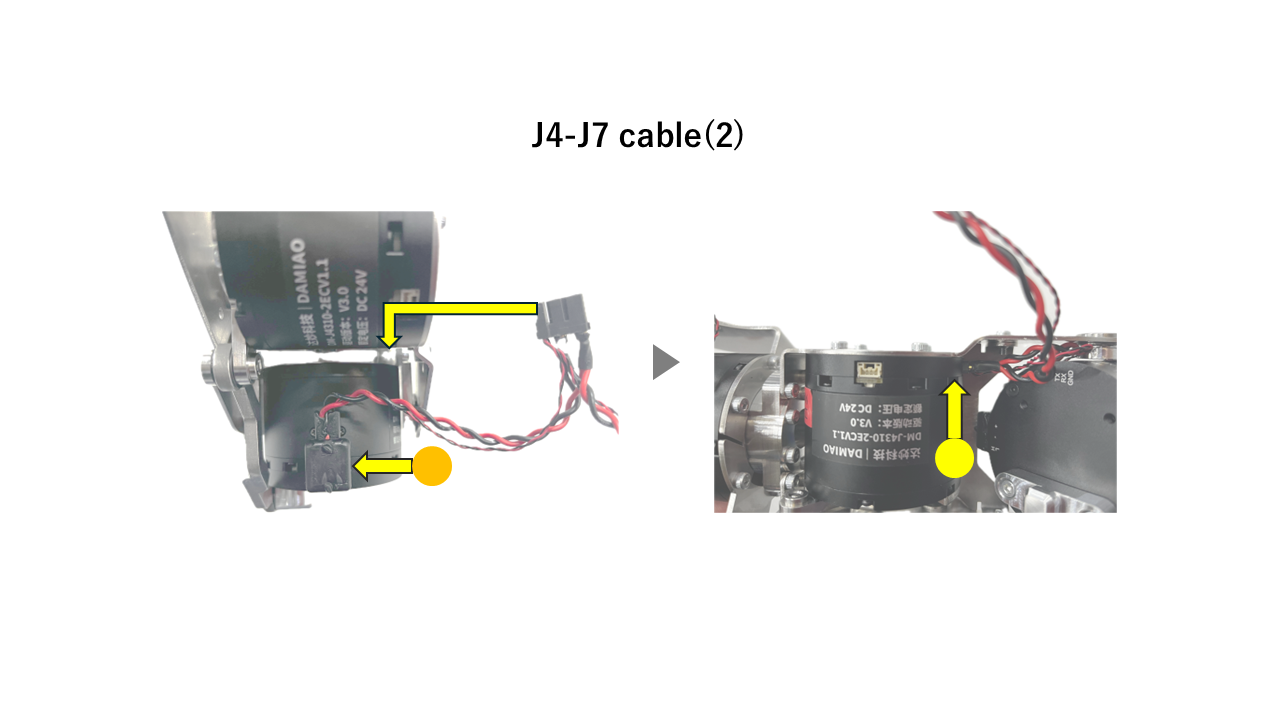
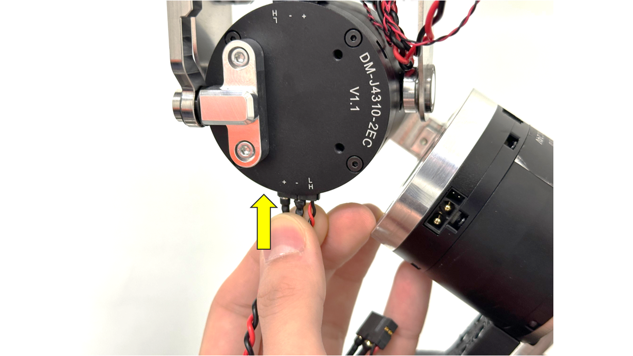
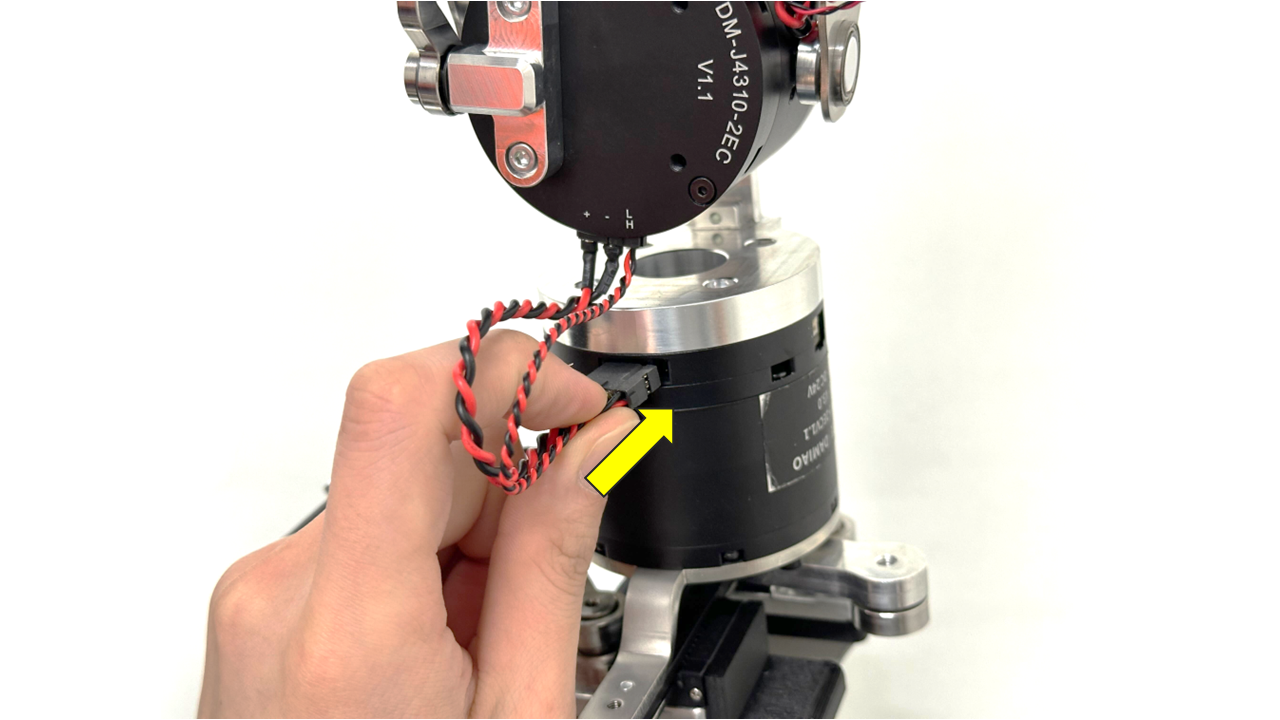
2. J4-J7 Wiring
Connect the J5 connector to the J5 motor from the back side of the arm. Then, bend the elbow to its stopping point and connect the J4 connector to the J4 motor. Make sure all cables are routed along the back side of the arm.
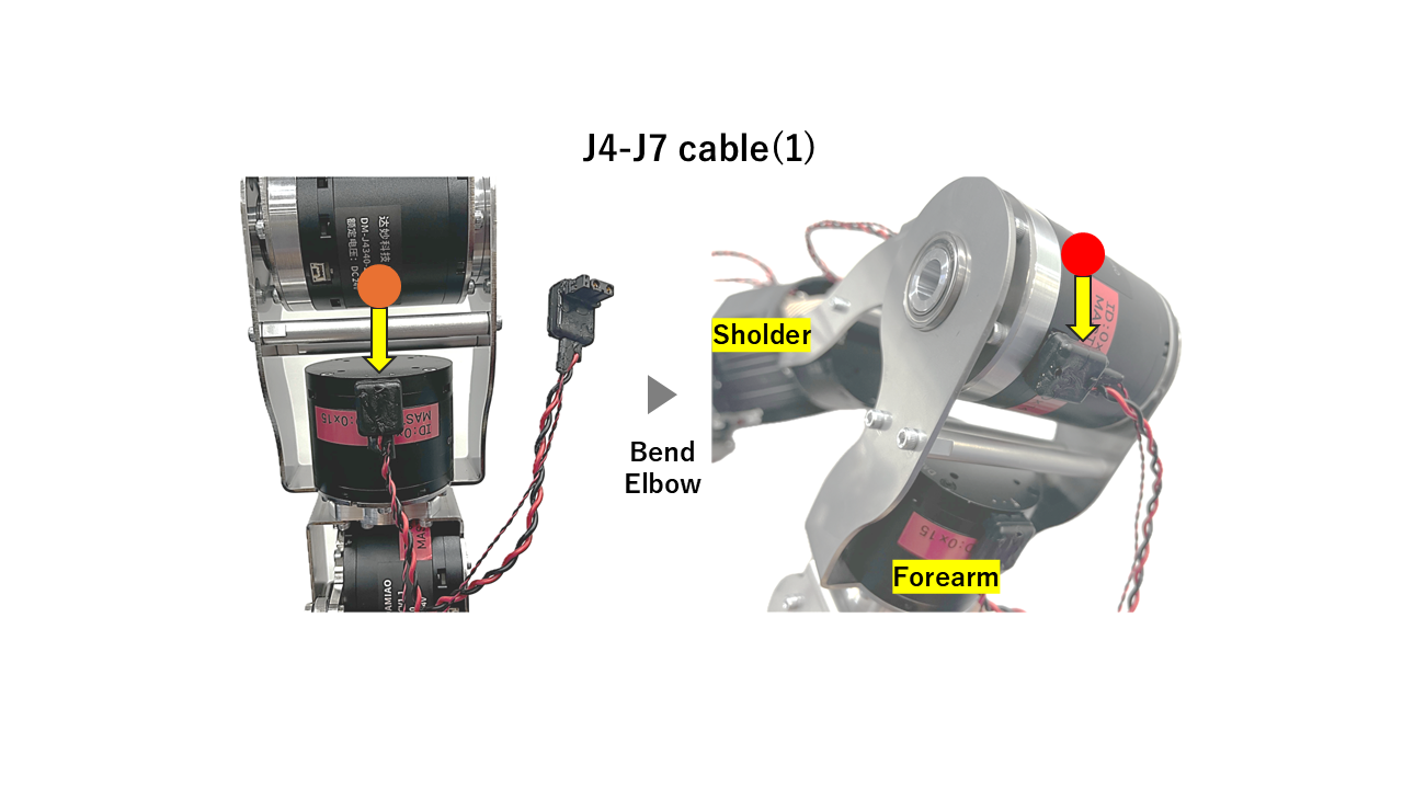
Connect the J6 and J7 connectors to the J6 and J7 motors, respectively. The J6 motor can be slightly difficult to access—try adjusting the arm position to find the best angle for plugging it in
3. J7-J8 Wiring
Connect the end-effector motor to the system. First, connect the J7–J8 cable to the underside connector of the J7 motor.
Then, connect the other end to the J8 motor.
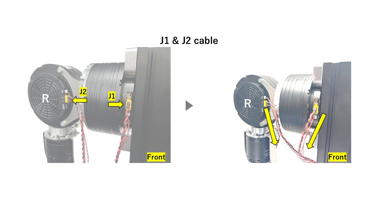
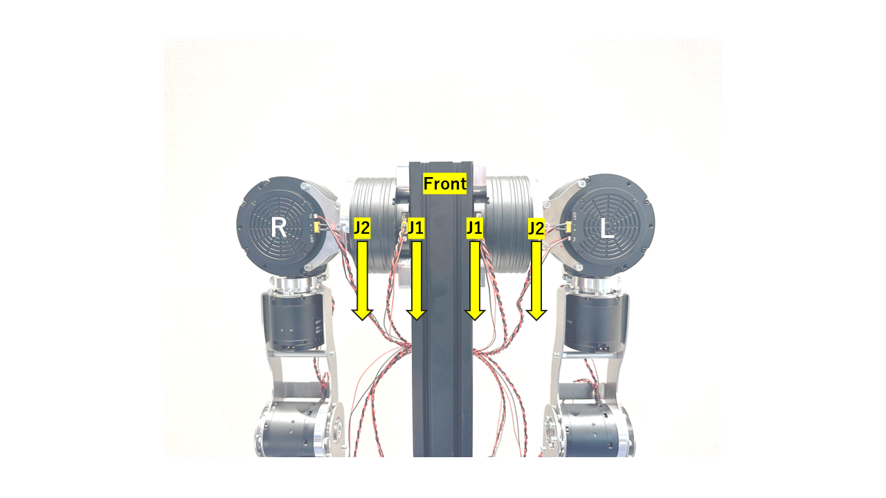
4. J1-J2 Wiring
Plug the J1 and J2 connectors into the J1 and J2 motors. Route the J1 cable through the robot’s armpit toward the back. Connect the J2 cable to the J2 motor, then bend the cable downward to ensure it’s properly routed.
Carefully connect the small white plugs on the J1 and J2 cables, as they may not fit securely if not aligned properly.