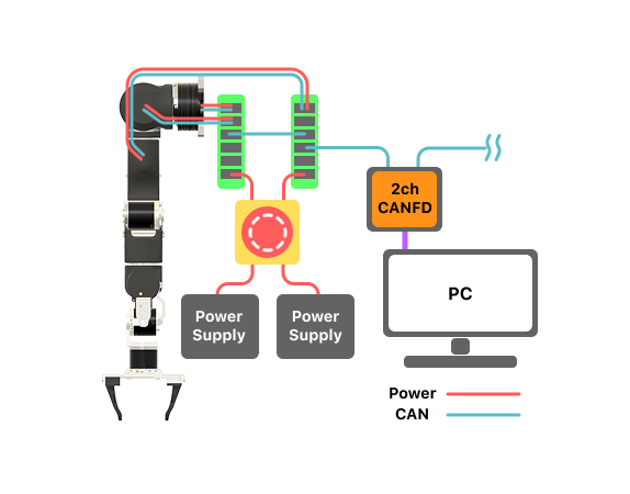
Power & CAN
Normal Setting
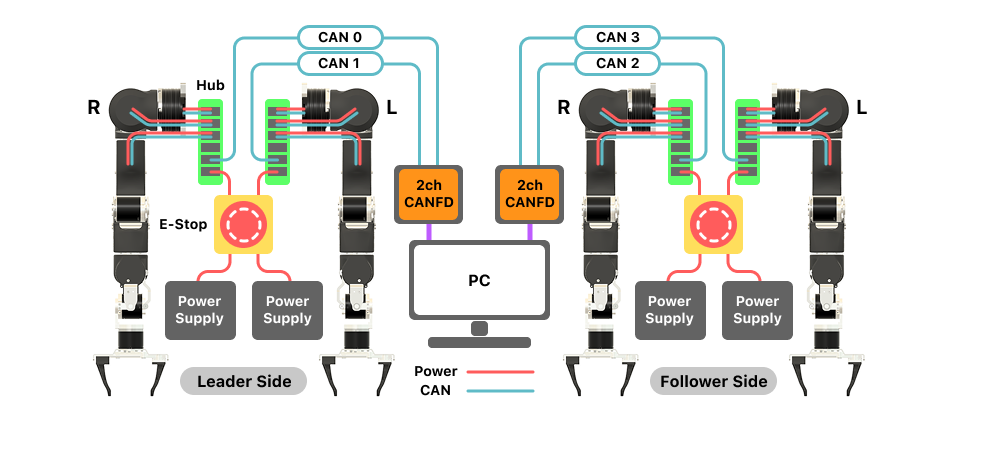
This installation guide provides instructions for setting up the leader-follower configuration of the OpenArm system. The leader and follower systems are physically identical, with the only distinction being the end-effector configuration.
Power
- Each of the four arms (two leaders and two followers) is powered by its own dedicated power supply.
- The system includes two emergency stop (E-stop) buttons — one for the leader pair and one for the follower pair.
- Connect the power supplies of the two follower arms to a single E-stop button. Repeat the same process for the leader arms, ensuring that each pair is connected to its designated E-stop.
- The two output cables from each E-stop should be connected to the corresponding hubs of the arms.
Communication
For the USB-to-CAN converters, assign the CAN IDs as follows:
- CAN ID 0: Right Leader
- CAN ID 1: Left Leader
- CAN ID 2: Right Follower
- CAN ID 3: Left Follower
Connect the red wires to CANH and the black wires to CANL. Then, plug each CAN connector into the hub of the corresponding arm.
Power Setting
For heavy payload handling, consider using two power supplies per follower arm. Connect J1 and J2 (the highest torque joints) to one dedicated power supply, and power the remaining joints (J3–J8) using a second supply. This configuration ensures stable performance under high-load conditions.