Arm Wiring & Casing
Arm Wiring
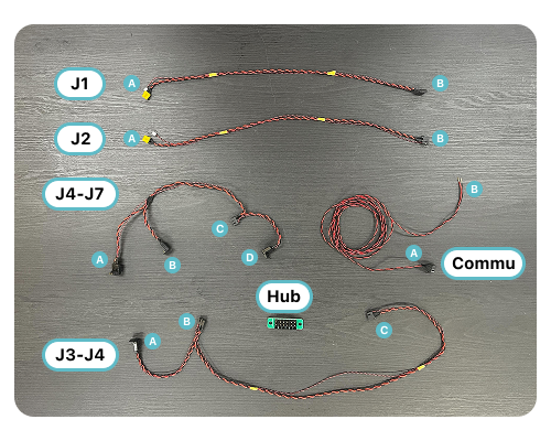
- The elements required to wire one arm are summarized in the following image. In this chapter, each cable is referred to by the name shown in the image, and the wiring process is described by the port number from A-D assigned to each cable. Note that the cables of J1 and J2 are the same component.
warning
Applying force to the cable to pull it out or insert it may cause damage. Keep a watchful eye on the cable to ensure that the connector part of the cable is grasped and inserted/removed.
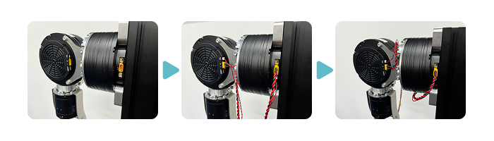
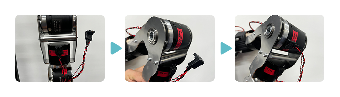
- Plug the A ports of the J1 and J2 connectors into the terminals of the J1 and J2 motors; turn the cable extending from the J1 motor through the underside to the back of the arm; turn the cable extending from the J2 motor so that it exits on the right side when the J2 motor is viewed from the back side.
warning
Carefully wire the small white connectors on the J1 and J2 cables as they may not plug in securely.
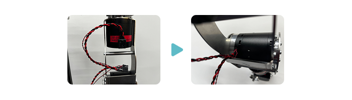
- Plug the A port of the J3-J4 cable into the connector on the back side of the arm of the J3 motor. Next, insert the B port of the J3-J4 cable into the connector on the J3 side of the J4 motor.
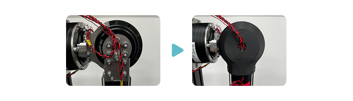
- Pass each cable through the hole in the cover of J2 while keeping the cable on the C port side of the J3-J4 cable and the cable on the B port side of the J2 cable centered on the output shaft side of the J2 motor.
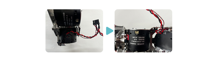
- First, insert the B port of the J4-J7 cable into the connector on the back side of the arm of the J5 motor. Next, insert the A port of the J4-J7 cable into the remaining port of the J4 motor with the arm folded down.
- Insert the D port of the J4-J7 cable into the port inside the arm of the J7 motor. At this time, it is easier to work by tilting the J7 motor to expose the port. Finally, insert the C port of the J4-J7 cable into the connector on the J7 motor side of the J6 motor. If it is difficult to reach, use tweezers.
- Plug the B port of the J1 cable, the B port of the J2 cable, and the C port of the J3-J4 cable into the hub. Next, insert the A port of the communication cable into the hub and connect the B port cable to the CAN device. Finally, connect the power supply to the hub to complete the wiring.

Casing
info
This chapter is in preparation. If you need information on casing assembly, please check from CAD data.